When working with wire‑stripping machines and soldering stations, recognizing various USB connector types is critical for smooth cable processing, repair, and custom‑cable assembly. Different USB plugs come in unique shapes and sizes, and mixing them up can lead to wrong stripping lengths, damaged cables, failed soldering joints, and wasted production time. Whether you repair old cables, build custom wiring harnesses, or run small‑batch cable assembly with your (wire‑stripping machine) and soldering machine, knowing these common USB interfaces helps you set correct machine parameters and get consistent finished results.
First, let us walk through the five mainstream USB connector types shown in the reference picture: USB‑A, USB‑B, Mini‑USB, Micro‑USB, and USB‑C.
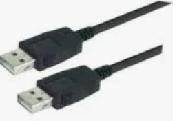
USB‑A is the most familiar rectangular standard plug. It is the classic flat, large‑sized male connector you see on most traditional chargers and computer host ports. Its wide, flat plastic shell has two metal notches on the metal shielding case. For wire‑stripping and soldering work, USB‑A cables usually contain 4 inner wires (power and data lines) plus a shielding braid. When feeding this cable into your automatic wire‑stripping machine, you need to set the stripping length to match the housing assembly requirement. Too long stripped wire will cause short‑circuit risks after soldering; too short will make it impossible to solder pins onto the connector terminal. After stripping, use your soldering machine to tin each copper conductor neatly before connecting to the USB‑A connector shell.
Next is USB‑B. This square‑shaped connector with beveled corners is widely used on older printers, scanners, and large‑size peripherals. Compared with USB‑A, its outer plastic housing is squarer and bulkier. USB‑B cables normally have thicker outer jackets. On your wire‑stripping machine, increase the blade depth slightly to cut through the thick outer insulation without nicking the inner copper wires. Pre‑tin all conductors with your soldering station before terminating to USB‑B pins. Misjudging this connector type will result in improperly stripped wire that cannot fit inside the USB‑B plastic housing.
Mini‑USB was popular on early‑generation digital cameras, old MP3 players, and early GPS units. It features a trapezoid‑shaped small plug with two symmetrical side chamfers. Mini‑USB is physically bigger than Micro‑USB. Many old‑stock repair projects still require re‑soldering Mini‑USB cables. Since its internal wires are relatively thin, you must lower the cutting pressure on your wire‑stripping machine. Excessive blade force will cut off fine internal strands. When soldering, use low‑temperature soldering tips to avoid melting the small plastic connector shell.
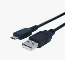
Micro‑USB once dominated Android smartphones, power banks, and small portable electronics. It has a narrow trapezoidal form, noticeably slimmer than Mini‑USB. Many repair workshops process large volumes of Micro‑USB cables. Its wire gauge is thin, so your wire‑stripping machine needs precise fine‑wire mode. After stripping, keep exposed copper short during soldering. Exposed loose strands easily trigger short‑circuit faults on compact Micro‑USB connector pins.
USB‑C, or Type‑C, is the modern reversible connector widely used in new phones, laptops, and fast‑charging devices. It has a symmetrical oval flat shape, allowing plug‑in from both directions. USB‑C cables are more complex: many contain extra E‑Marker communication wires besides standard power and data lines. This means you cannot use the same stripping parameters you apply for older USB cables. On your wire‑stripping machine, adjust stripping length carefully to avoid damaging extra thin signal wires. When you operate your soldering machine for USB‑C assembly, work slowly. Its pin pitch is extremely tight; careless soldering creates cold‑joints or solder‑bridge shorts between adjacent pins.
How do you match these connectors to your wire‑stripping machine and soldering machine workflow?
Step one: visually identify the USB connector before production. Check the outline shape, width, and notch features to confirm which USB type you are working with.
Step two: adjust your wire‑stripping machine's blade height, stripping length, and feed speed according to the cable thickness and wire count of that specific USB cable. Thick USB‑B cables need deeper cuts; thin Micro‑USB and USB‑C cables need lighter blade pressure.
Step three: after stripping insulation, inspect copper strands for nicks. Then use your soldering machine to apply uniform tin to each wire.
Step four: solder wires onto the corresponding connector terminals, assemble the plastic housing, and complete testing.
Common mistakes to avoid: confusing Mini‑USB and Micro‑USB because of their similar trapezoid look. Setting identical stripping parameters for all USB cable types. Applying too‑hot soldering tips that melt small connector plastic. These errors cause high defect rates in cable assembly.
In conclusion, visual identification of USB‑A, USB‑B, Mini‑USB, Micro‑USB and USB‑C is the first step for reliable cable processing. Correct identification guides you to configure suitable settings on your wire‑stripping machine and soldering machine. Good recognition skill reduces defective products, improves assembly efficiency, and guarantees stable quality for your cable‑building and electronic‑repair jobs.