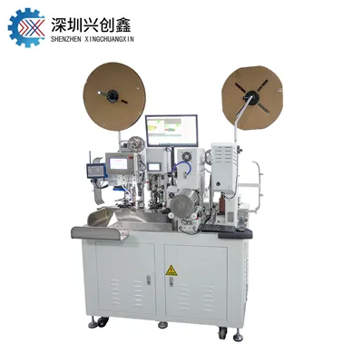
Terminal crimpingis a core process in wire harness manufacturing. Its working principle can be broken down into the following key stages:
I. Basic Workflow
Feeding and Positioning Stage
The wire is precisely conveyed to the crimping position by the wire feeding mechanism.
The terminal is fed into the mold cavity via a vibratory bowl feeder or carrier tape.
Optical sensors verify the alignment accuracy between the two (error typically ≤0.1 mm).
Crimping and Forming Stage
The upper die descends and contacts the terminal.
Plastic deformation begins when the pressure reaches the preset value (typically 2–20 tons).
The terminal wings wrap around the wire along the designed trajectory.
Holding and Setting Stage
The maximum pressure point is maintained for 0.2–0.5 seconds.
This eliminates the effect of material spring-back.
It ensures the complete rearrangement of the metal crystal lattice.
Quality Inspection Stage
Real-time monitoring of the crimping force curve (normal range ±15%).
Automatic continuity testing (resistance value ≤5 mΩ).
Visual system inspection of the crimped appearance.
II. Core Mechanical Principles
Cold Welding Effect
At a pressure of 6–8 kN/mm², copper achieves a 30%–50% compression ratio.
The metal crystal lattices interpenetrate to form a metallurgical bond.
Strain Hardening Mechanism
The terminal material undergoes work hardening.
Hardness increases by 20–30 HV.
Tensile strength improves by 15%–25%.
Air-Tightness Formation
The wire lay-up ratio is maintained at 85%–95%.
The gap between terminal and wire is ≤0.05 mm.
The oxidation-prevention film is effectively disrupted.
III. Key Structural Roles of the Mold
Guide System
Linear guide rail accuracy: 0.01 mm/m.
Ensures upper and lower die coaxiality ≤0.02 mm.
Cavity Design
Transition arc radius (R corner): 0.1–0.3 mm.
Unfolded-length error: ±0.05 mm.
Surface roughness: Ra 0.4–0.8 μm.
Stripping Mechanism
Spring ejection force: 3–8 kg.
Air-assist pressure: 0.3–0.6 MPa.
IV. Key Process Parameter Control Points
|
Parameter Category |
Control Range |
Effect |
|
Crimping height |
±0.03 mm |
Determines conductivity and mechanical strength |
|
Crimping speed |
30–60 mm/s |
Affects forming quality and efficiency |
|
Holding time |
0.3–0.8 s |
Eliminates material spring-back |
|
Crimping force |
Rated value ±10% |
Ensures connection reliability |
V. Quality Verification Standards
Mechanical Performance Testing
Pull-force test (≥ the wire's rated tensile force).
Bend test (±90°, 10 cycles each, no fracture).
Electrical Performance Testing
Contact resistance (≤1.5× the wire resistance).
Current cycling test (1,000 cycles, ΔT ≤30 K).
Microscopic Inspection
Metallographic cross-section (compression ratio 30%–80%).
SEM scanning (integrity of metal flow lines).
Modern high-end crimping molds have integrated force–displacement dual closed-loop control systems, which can compensate in real time for material thickness fluctuations (±0.05 mm automatic adjustment). Combined with an MES system, full-process traceability of every crimping point can be achieved. Correctly understanding and controlling these principles and parameters is key to ensuring the reliability of terminal connections.