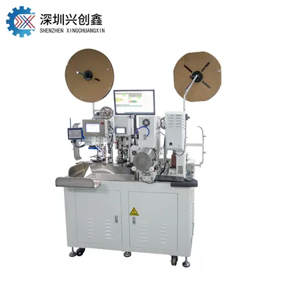
Working Principle of the Computerized Wire Stripping Machine
Brief introduction to the functions of key components:
1 Inlet Wire Roller: Transports the wire and strips the wire ends. When processing short wires (length < 50mm), it strips both the leading and trailing ends. During intermediate stripping operations, it strips the leading end as well as specific sections along the middle of the wire.
2 Outlet Wire Roller: Transports the wire and strips the trailing end. (This roller is inactive when processing short wires; the "outlet roller lift knob" must be set to the "u" position.)
3 Inlet Roller Gap Adjustment Knob: Adjusts the gap between the inlet rollers; rotating upwards increases the gap, while rotating downwards decreases it (adjusted based on wire thickness).
4 Inlet Roller Pressure Adjustment Knob: Adjusts the pressure applied by the inlet rollers. Pull the knob out and rotate clockwise to increase pressure, or counter-clockwise to decrease pressure. (Adjust based on the insulation's toughness-i.e., the difficulty of stripping; increase pressure for tougher insulation and decrease it for softer insulation.)
5 Inlet Roller Lift Knob: Lifts the inlet rollers to allow for wire threading. Rotate clockwise to lift the rollers for smooth wire insertion; rotate counter-clockwise during operation to lower the rollers and clamp the wire.
6 Outlet Roller Gap Adjustment Knob: Adjusts the gap between the outlet rollers; rotating upwards increases the gap, while rotating downwards decreases it (adjusted based on wire thickness).
7 Outlet Roller Pressure Adjustment Knob: Adjusts the pressure of the outlet rollers. Pull the knob out and rotate it counter-clockwise to increase pressure, or pull it out and rotate it clockwise to decrease pressure. (Adjustment is based on the insulation strength-i.e., the difficulty of stripping the wire; increase pressure for tougher insulation and decrease it for softer insulation.)
8 Outlet Roller Lift Knob: Raises the outlet rollers to allow for wire removal. Rotate the knob counter-clockwise to raise the rollers for easy wire removal; rotate it clockwise to lower the rollers for operation. (The outlet rollers should be raised when using the short-strip program.)
9 Blade Holder Assembly: Responsible for cutting the wire and stripping the ends (head and tail). When the machine is stopped, the upper and lower blades must be fully opened to allow the wire to pass through the cutting mechanism smoothly.