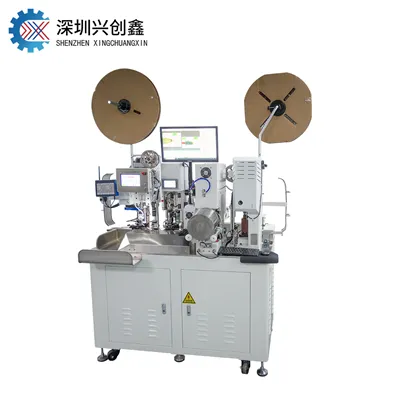
High‑speed Ethernet wire harnesses (including automotive SPE Single‑Pair Ethernet, Gigabit automotive Ethernet and industrial high‑speed Ethernet) feature differential high‑frequency signal transmission. Their core constraints lie in signal integrity, consistent impedance, shielding integrity and differential‑pair balance. Conventional low‑speed wire harnesses only focus on continuity, insulation and pull‑off force. Minor processing defects barely affect low‑speed signals. However, tiny deformation, stripping damage or crimp offset in high‑speed harnesses will trigger impedance deviation, excessive return loss, crosstalk and eye‑pattern failure, resulting in communication packet loss or disconnection. This brings brand‑new upgrades in precision, processing technology and inspection dimensions for stripping, crimping and testing equipment, as detailed below.
1. New Requirements for Stripping Equipment (Cutting‑Stripping & Shielding Processing)
High‑speed Ethernet cables adopt multi‑layer structures: outer jacket, aluminum foil/braid shield and foamed‑insulation twisted differential pairs. Conductors are fine‑gauge wires of 26‑32 AWG, and foamed insulation is highly susceptible to deformation under compression, which will directly impair impedance characteristics.
Greatly tightened stripping precision
Stripping‑length tolerance is tightened from ±0.5 mm for conventional harnesses to ±0.1‑0.2 mm. The length difference between stripped ends of the two differential wires must be strictly controlled. Misaligned stripping ends will directly cause excessive differential skew and impedance imbalance.
Closed‑loop‑controlled stripping depth: nicks, scratches or broken strands on individual copper conductors are prohibited. Squeezing or scratching of foamed insulation is forbidden, as changed dielectric thickness will shift the target differential impedance of 100 Ω ±10 Ω. Conventional mechanical‑blade stripping tends to damage shielding foil and foamed insulation. Laser stripping is preferred; mechanical‑blade units shall be equipped with closed‑loop servo depth control plus visual feedback.
Capability for multi‑layer sequential stripping Sequential stripping for outer jacket → shielding layer (aluminum foil / braid) → inner insulation is required. Shielding layers must not be torn or fractured, and aluminum foil must stay intact. Shielding‑wire processing is critical for high‑speed Ethernet. Braid strands shall not fray or short‑circuit signal conductors. Equipment shall support shielding‑layer folding, shaping and pre‑grounding without rough pulling that damages shielding structures.
Clamping and tension control for cables Soft foamed insulation demands flexible fixtures with low clamping pressure. Closed‑loop tension control for cable feeding prevents stretching of twisted pairs and distortion of twist pitch. Altered twist pitch directly drifts differential impedance. Cables shall not be twisted during processing to preserve original twist geometry.
Pre‑stripping and post‑stripping in‑line visual inspection Post‑stripping vision checks include cut‑end flatness, conductor nicks, shielding‑layer damage, stripped‑end length offset of differential pairs and residual insulation debris. Defective units shall be rejected before entering crimping stations.
Pain point: Conventional stripping machines only ensure jacket removal, without consideration for shielding integrity, twist‑pitch preservation and synchronized stripping of differential pairs. Direct processing of high‑speed Ethernet cables yields many latent communication failures: products look intact yet fail high‑frequency tests.
2. New Requirements for Crimping Equipment (Signal Terminal & Shield‑Ground Terminal Crimping)
High‑speed Ethernet harnesses require two crimping processes: differential‑signal‑terminal crimping and shield‑ground‑terminal crimping. Conventional crimpers only monitor crimp height and pull‑off force. Beyond mechanical performance, high‑speed applications demand controlled coaxiality and uniform deformation to guarantee high‑frequency impedance and EMC performance.
Closed‑loop servo crimping with higher precision grade
Crimp‑height tolerance is tightened from ±0.05 mm for conventional harnesses to within ±0.02 mm. Force‑displacement curve monitoring (CFM) is mandatory for real‑time waveform logging throughout crimp cycles; alarms trigger for anomalies, and full‑process data traceability per cycle is required.
High mold coaxiality: Cables, terminals and dies must maintain strict coaxial alignment with offset ≤0.1 mm. Misalignment causes one‑sided compression, uneven conductor deformation and impedance discontinuities that reflect high‑frequency signals.
Process support for simultaneous dual‑wire differential‑pair crimping For SPE Single‑Pair Ethernet (one differential pair), equipment shall ensure consistent crimp status for both conductors. Deviations in crimp height and compression ratio between the two wires must be tightly limited to avoid partial under‑crimping.
Special requirements for shielding‑terminal crimping When crimping braided‑shield / aluminum‑foil onto ground terminals: excessive shielding‑strand fracture shall be avoided while low‑impedance shielding contact is guaranteed. Frayed shielding strands shall never bridge signal conductors, otherwise intermittent short‑circuits and severe EMI will occur. Dedicated dies for braid crimping are required; conventional signal‑terminal dies cannot be reused.
Integrated post‑crimp in‑line visual inspection 2D / 3D vision checks cover conductor strand overflow, broken strands, flare‑condition status, insulation‑crimp positioning and short‑circuit risks from protruding shielding strands. Pull‑force sampling alone cannot identify latent defects where pull‑force passes but high‑frequency performance fails.
Quick die change and recipe management Multiple cable specifications exist for SPE, MATEnet, GEMnet and other high‑speed Ethernet standards. Equipment shall store multiple process recipes for fast switching between production runs to prevent process drift caused by manual commissioning.
Key distinction: For low‑speed harnesses, qualified crimping equals sufficient pull‑off force. For high‑speed Ethernet harnesses: satisfactory pull‑off force does not guarantee qualified high‑frequency performance. Uneven crimp deformation creates impedance discontinuity points. Parts may pass visual and pull‑force tests yet fail return‑loss and eye‑diagram tests.
3. New Requirements for Testing Equipment: from Continuity‑Insulation Test to Comprehensive Test Combining Mechanical, Electrical and High‑Speed Signal‑Integrity Performance
Traditional harness testers only perform continuity, short‑circuit and insulation‑withstand‑voltage tests, which cannot cover main failure modes of high‑speed Ethernet. Additional high‑frequency signal‑integrity testing, shielding‑performance evaluation and comprehensive in‑line machine‑vision inspection are mandatory.
3.1 In‑line Machine‑Vision Inspection (Full‑coverage Pre‑test Inspection)
After stripping: stripped‑end length offset, conductor nicks, shielding‑layer tearing, aluminum‑foil damage and frayed strands.
After crimping: terminal‑crimp profile, overflowing conductor strands, short‑circuit risks from protruding shielding strands, crimp flare and terminal deformation.
3D laser profile scanning detects minor deformations invisible to 2D cameras.
3.2 Basic Conventional Electrical & Mechanical Performance Tests
Continuity, short‑circuit, insulation resistance and dielectric‑withstand‑voltage tests.
Terminal pull‑off force test.
Cross‑section analysis (first‑article / sampling inspection): observe internal conductor‑crimp compression and detect voids or fractured copper strands.
3.3 Specialized High‑Frequency Signal‑Integrity Testing (Core New Requirement for High‑Speed Ethernet)
This represents the biggest difference versus conventional harness testing. Test systems built around Vector Network Analyzers (VNA) are required:
Differential‑impedance measurement (target 100 Ω) to monitor impedance fluctuation and identify impedance discontinuities at stripping and crimping points.
Return loss and insertion loss.
Differential‑pair skew: excessive time offset between the two wires corrupts high‑speed communication.
Near‑End Crosstalk (NEXT) and Far‑End Crosstalk (FEXT).
Shielding‑performance testing: coupling attenuation and shielding attenuation, critical for EMC immunity in 30‑600 MHz automotive‑Ethernet applications.
Note: High‑frequency testing is divided into offline lab‑based first‑article testing and simplified in‑line production‑floor testing. 100 % full‑unit VNA testing on mass‑production lines incurs high costs. Industry practice: complete VNA signal‑integrity tests for first‑article and batch sampling; production‑line quality is secured via strict process control, vision inspection and force‑displacement monitoring.
3.4 Full‑process Data Traceability
Equipment shall bind cutting‑stripping parameters, crimping force‑displacement curves, vision‑inspection results and test data to harness barcodes, upload data to MES systems and realize full‑process traceability per individual harness for root‑cause analysis of impedance anomalies.
4. Overall Additional Equipment‑Level Requirements
Environmental stability: Production‑floor temperature‑humidity stabilization and equipment vibration damping are required. Vibration degrades precision of laser stripping and servo crimping and induces impedance drift.
Flexible fixtures: Low‑damage clamping for fine twisted differential pairs, avoiding foamed‑insulation compression and twist‑pitch distortion.
Reduced operator dependency: Process parameters shall be solidified in software to minimize manual commissioning and prevent batch‑level high‑frequency defects.
Multi‑specification compatibility: Support STP shielded Single‑Pair Ethernet, UTP unshielded cables and other high‑speed cables of different wire gauges.

Summary Comparison Table
| Items | Conventional Low‑Speed‑Harness Equipment | High‑Speed‑Ethernet‑Harness Equipment |
|---|---|---|
| Stripping focus | Complete jacket removal; avoid cutting thick copper wires | Stripped‑end length offset, shielding integrity, foamed‑insulation protection, twist‑pitch preservation, prevention of micro‑nicks on copper conductors |
| Crimping focus | Crimp height and pull‑off force | Crimp height plus force‑displacement curve monitoring, coaxiality control, both signal‑terminal and shield‑ground‑terminal crimping, differential‑pair consistency control |
| Testing methods | Continuity, insulation and pull‑force test | Full‑coverage vision inspection + mechanical‑performance test + VNA‑based high‑frequency signal‑integrity test (impedance / return loss / skew / shielding attenuation) |
| Typical failure modes | Open circuit, short circuit, pull‑off failure | Latent failures: parts pass visual and pull‑force tests yet suffer impedance jump, excessive return loss and communication packet loss |